
Angstrom Sputter System
Description
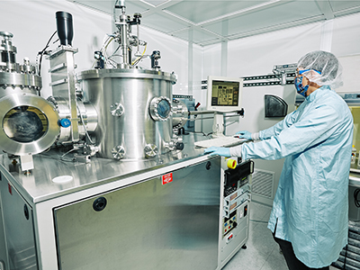
The Angstrom Sputter System is a load locked sputtering deposition system for R&D applications. It can be used to deposit thin metal or dielectric films from three MAK 3” sputter targets powered by two 1000W RF and one 1000W DC power supplies. The MAK guns are also capable of sputtering magnetic materials.
|
Process gases: |
Ar, N2, O2 | |||
|---|---|---|---|---|
|
Sputter targets and processes: |
Aluminum,Carbon,Chromium,Cobalt,Copper,Gold*,Iron Nickel,Nickel Oxide (reactive),Permalloy (80%/20%),Silicon (undoped or doped),Silicon Nitride (reactive),Silicon Dioxide, Titanium,Zirconium |
|||
|
*Additional usage fees exist for precious metal targets. At this time other targets available from MMF users are Indium Tin Oxide and Nickel. |
||||
Processes
Aluminum thin film
- Thin films of aluminum can be deposited via sputtering or evaporation.
Chrome thin film
-
Chrome RF sputter deposition.
dep rate= 9.4nm/min, power=400W RF, pressure=10mT Argon, substrate height =120
Gold thin film
- Thin films of gold can be deposited via sputtering or evaporation. Ebeam and resistive thermal evaporation are available.
Iron thin film
- Thin films of iron can be deposited via sputtering.
Permalloy thin film
- Thin films of permalloy can be deposited via sputtering.
Silicon Dioxide thin film
- Thin films of silicon dioxide can be deposited via sputtering.
Titanium thin film
- Thin films of titanium can be deposited via sputtering.
Operating Manual
*Note that the instructions below may not contain the most recent updates. Please refer to the manuals printed and posted at the equipment.
System Overview
Thisphysical vapor depositionsputter tool isa researchgrade instrument withthree targets,two RF power supplies, one DC power supply, substrate heating, and multiple process gases.
Safety
- This tool contains high voltage sources. Do not go behind the tool, attempt to open covers, or work inside the tool.
- Avoid pinching your fingersin theload lockdoor.
- Use caution to avoid bumping your head when the door is openor on the transfer arm.
- After long depositions, the sample stage may be very hot. Use caution.
- If the tool is on fire orif someone is in immediate danger, hit theemergency stopon the front of the tool.
Allowed Materials and Processes
- Target link: (inprogress)
Restricted Materials and Processes
- Do not attempt to make your own recipes without extensive training and permission from the lab manager.
1. Check tool statusand configuration
- Visit http://www.mmf.montana.edu/equipment-status.html.
- Request different targets,shields,or gases as far in advance as possible, preferablyat leasttwoweeks,by emailing the lab managerand mmfstaff@montana.edu.
2. Check tool reservations for conflicts and reserve
the tool
3. Check lab status
- Turn on N2for the lab and checkthe house N2 bottle pressure.If it is below 300 PSI, reportthe shortage tostaff.
- Check process gas bottle pressures (Ar,O2,N2).
If any are below 300 PSI, report the shortage to staff. - Checkthat the correctprocess gas is selectedfor your process.O2and N2 can be switched;request a change with staff if necessary. Do not attempt this processwithout explicit training from the staff and accompanying documentation. It is very easy to contaminate the gas lines.
4. Log into SUMS
5. Equipment checks
- Checkdeposition chamberpressure.The ion gaugeshould read <5e-7Torrif left overnightor<1e-6Torrif recently used.Theconvectronandbaratrongauges should read “Off Scale”.
- Checkthatthecryotemperatureis below 14K.If the temperature is <18K, use the tool but report the problem to the lab manager. If the temperature is >18K, do not use thetool.
- Checkload lock pressure
- Convectronshould read “Off Scale."
- Note:thereis noion gauge connectedto the load lock,so this reading is meaninglessand can be ignored.
- Double checkthetarget configuration by selecting “BASE FLANGE DETAIL."
- Checkmass flow control settings
- Check which gases arecurrentlyconnectedto the tool.Ais always connected, but N2or O2canbe selected. Check the valve on the wall behind the toolunder the pressure gauges on the inside of the wall.
- Check theMKS 4 Channel Readout. Any channel set to “Rem” will turn on during a process.Aris connected tochannel 1, and either N2or O2is connected to channel 3. For most processes, onlyAris used, so the other channels should all be in the “Off” position.
- Check pressure control settings
- The VAT Adaptive Pressure Controller should have the “Remote” and “Open” LEDs on.If “Local” is lit, press and hold “Remote” until that LED turns on. You may need to reset a fault on the Angstrom software.
- Check power supplies
- Check that the required power supplies are on. The RF supplies should be on and should read “Remote OFF” in the upper right corner. They should also read “auto” under the diagram of the matching capacitors.
6. Load samples
- Load samples onsample holder.Note that most of thethicknessvariability will be radialbecause of sample rotation,so expect thickness variations from the center to the edge of the sample holder.Verify that all screw holes are coveredand that all screws arefully tightened down. You are welcome to use screws or Kapton tape to secure your samples.
- Vent load lock
- Unscrew and unlatch blue knob on load lock.
- Select “AUTO”,then“LOAD LOCK AUTO VENT MODE SELECTED”
- Click “SELECT” on verification
- Click “START SELECTED CYCLE”
- Load sample stage in load lock
- Set stage inthebayonet mount.
- Orient screw toward you.
- Raisesample stage all the way upif you plan to do load lock sputtering.
- Pump load lock
- Closethedoorand gently tighten thehandle.
- Select “AUTO”and then "LOADLOCK FULL PUMP DOWN MODE SELECTED”
- Click “START SELECTED CYCLE”
- Wait forload lock convectrongauge to read “Off Scale."This happens a few minutes after the automatic process is complete.
7. Clean sample in load lock (optional)
- Ensure the sample stage is all the way up.
- Enter manual modeby selecting “MANUAL."
- Close the “LL HIGH VAC VALVE” and open the “LL GATE VALVE”.
- Run MMF-LoadLockor other cleaning process.
8. Transfer sample
- Ensure load lockconvectrongauge reads “Off Scale”.
- Open “LL GATE VALVE."
- Turn on lamp.
- Make sure ruler on top of chamber (stage height ruler) isset to 85mm.
- Carefully and smoothly move the transfer arm all the way into the load lock.
- Lower the sample stage onto the transfer arm fork. Do this slowly and carefully, while making small adjustments to the rotation and transfer arm position. If the fork starts to bend downward, stop andassess.Make sure the stage sits flat on the fork.When the sample stage is resting on the fork, raisethebellows so that the sample stage can be moved into the main chamber.
- Carefully and smoothly move the transfer arm to the main chamber transfer position.
- Use the motorized stage tolower the main chamber bayonet mount and lift the sample stage.
- Fully retract the load arm.
- In manual mode,close the “LL HIGH VAC VALVE” and “LL GATE VALVE”.
- Lower or raise the sample stage to the desired height for deposition.
9. Deposit
- Open the appropriate database and select the desired process. Do not edit anything but the process time in the MMF-Standard-Recipes database.
- Edit the process if necessary.
- Click “START PROCESS”
- Monitor the tool during ramp up and during the deposition.
- Verify that the plasma strikes. If it does not by the time the supply reaches about 100 W, stop the process. See the troubleshooting section.
- After the plasma strikes, close theview portshutter slowly. If thisshutter is opened or closed quickly, it can get stuck.Open it periodically to view that the process is proceeding as expected.
- Verify that thesource shutter openswhen process startsand that the stage is rotating.
- Verify that the reflected power decreases to <5 W and remains at that level during the deposition.
- Verify that the sample shutter opens after the ramp and hold steps.
10. Unload sample
- After the deposition,wait for the sample temperature to read <70 C on the “SAMPLE HEATINGreading next to the EMO.Below the angstrom engineering sign.
- Raise the sample holderback to 85 mm.
- Move the transfer arm back to the main chamber’s loading position.
- Set sample holderonto transfer arm’s fork using the z-height controller and rotation knob.
- Once the sample holder is loaded onto the transfer arm’s fork, open the load lock gate valve and move the sample holder tothe load lock’s unloading position.
- Unload the sample holder and fully retract the transfer arm.
- Select "load- lock auto vent” and wait for the cycle to complete.
- Once the load lock is completely vented, open the load lock’s door and remove the sample holder.
11. If finisheddepositing,close the load lock’s door and tighten the blue knob. Select full pump down andletcycle complete.
Troubleshooting
- Chamber will not vent.
- Ensure lab N2 is onand hasenough pressure.
- Cryotemperature isbetween 14 and 18K
- Use the equipment but report the problem to the lab manager.
- Cryo temperature is >18K
- Do not use the tooland report the problem to staff.
- Processaborts with "Sigmahasselecteda wrong combination “FAULT”
- Acknowledge and reset the fault.
- Look for interlocks which may not be met for depositing.
- Check recipe for accidentally changed or incorrect values.
- Tool reads “System Disabled – LogInOnSUMS to Enable”
- Log into SUMS andinto the tool. If this does not work, contact staff.
- Process aborts with“Gate Valve is Faulted”
- In manual mode,
- Sample shutter did not open during deposition
- Check recipe
- Plasma did not strike
- Pressure might be too low. Change source numberdown.
- This message appears when attempting load lock vent: cycle stop has been requested faultAcknowledge error, go back to software home screen (might have to close previous window), acknowledge and reset fault.After doing this, if gate valve is still yellow, enter manual mode and open gate valve.